

It is combined with a fine water entry. Slicing through water and waves, rather than bobbing over them, that’s what we are after. Will it result in a slightly wetter ride? Probably, but it will create a more comfortable movement and a shorter net route between departure and destination.
The underwater ship broadens towards the mid-section, where the beam over water is at its widest: 4m20. A narrow ship, or LDL-designed ship, which stands for “low displacement to length ratio”. What the goal of LDL-design is? Primarily better efficiency. Better efficiency results in lower diesel fuel usage results in smaller needed tanks results in lower weight, which – in turn – further lowers diesel fuel usage …
For the keel, we decided for a long, full and sturdy design. A shorter one would have been good enough, and would have resulted in a lower total wetted area, resulting in further efficiency gains. We decided not to go there, but embraced the larger and sturdier design. Why? First, we expect the added course and roll stability will – in real life scenario’s – outweigh the benefits of focussing on “just” efficiency. Secondly, the sturdy and long, full keel helps the ship when beaching. Yes, it can beach.
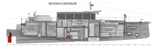
The ship is 1m25 deep. Deepest at the propellor window, of course. The canoe body only sits at 0.9 meters. The main tank sits just behind the engine. Two wing tanks sit next or slightly in front of the engine. In full-load situations, the ship tilts a little bit forward, reducing the shaft angle, improving efficiency. At half- or light-load conditions, it is only the main tank that’s full or partially full. As it sits behind the engine, the 1 degree tilt forward is no longer there, but replaced with a 1 degree tilt backwards in order to keep the prop as low in the water as possible. Again, to optimize for fuel efficiency in half- or light-load sailing.
The aft part of the underwater ship consists of two main parts. First, the ascending part, then the descending bit near the transom. Descending transom, Why? Next paragraph, please! First, let’s dive into the ascending aft part of the hull. We designed it to ascend at a low angle. This helps the water stick to the hull (more efficient) and allows for higher speeds through the water. As in “higher than hull speed”. We find this important, not just for efficiency, but also because it helps the LM65h accelerate down waves, preventing broaching as much as possible. A “slower” ship drags and brakes when it is pushed down a wave too fast, increasing the chances of broaching. This design offers the contrary. Means the LM65h can easily speed up to 14 knots, down-wave. Please note that her cruising speed will be 10 knots and her top speed – in calm water – 11 to 11.5 knots, depending on load.
Now onwards to the descending last bit of the underwater ship, aft. It descends to help the LM65h generate lift aft. This is important because, as a ship approaches hull speed, the forward sections create lift. Since a ship sits in the water, this lift “rotates’ the aft section deeper into the water. And since the aft section is wider, drag numbers “explode” and efficiency is lost. For LM65h, to achieve its high cruising speed at very economical diesel fuel usage numbers, we invented (and heavily researched) this solution and the exact execution via (amongst others) CFD. It works. It helps achieve an overall diesel consumption, at 10 knots, of 1 liter per 1 kilometer travelled. With the 7,000 liter fuel tanks, this results in a hefty action radius …
All right, the last design that we wanted to optimize what the transom itself. It is designed to take advantage of wave energy. LM65h can surf and take advantage of following seas.
That’s it for now. I hope you like the info shared!


